 by
by Wow, it’s been a crazy few months. I am taking some courses for my masters, started a few contracting gigs and went to China with DangerousPrototypes Hacker Camp. There is so much to write about and I’ve been dropping the ball on Protological. Time to change that. Time for some cool LED stuff!
While in China I picked up a 5 meter “5050” 12V LED strip with 30 LEDs per meter for 90RMB which is $14.50 USD. I didn’t buy the controller because I wanted to control it with a microcontroller of course! The controller chip is a knockoff LPD6803 LED driver chip that listens for clocked data. The only datasheet I could find was from Adafruit here and the english is really, really bad. I didn’t know ‘grey’ == ‘color’?! After some playing around I figured out the protocol for how the data is sent. The commands are 16-bit and shifted out MSB first, the clock is idle low and the data is latched in on the high transition of the clock. The MSB is always 1 to indicate that the value is data and the 3 colors are 5 bits each; allowing for 31 steps in brightness.
1000 0000 0000 0000
D|Col1||Col2||Col3|
One would think that the colors are Red, Green and Blue, however some testing showed they are Green, Red and Blue.
1000 0000 0000 0000
D|Grn ||Red ||Blue|
So if you want to turn on an LED with 1 step of RGB the byte value is 1 00001 00001 00001 = 1000 0100 0010 0001 = 0x8421;
These strips can be chained together, so to ‘reset’ the strip pixel ID and have it listen for a new set of colors you send 32 0’s which is 8 bytes of 0x00. Once I got the protocol figured out it was really easy to hook up a micro and control the strip.
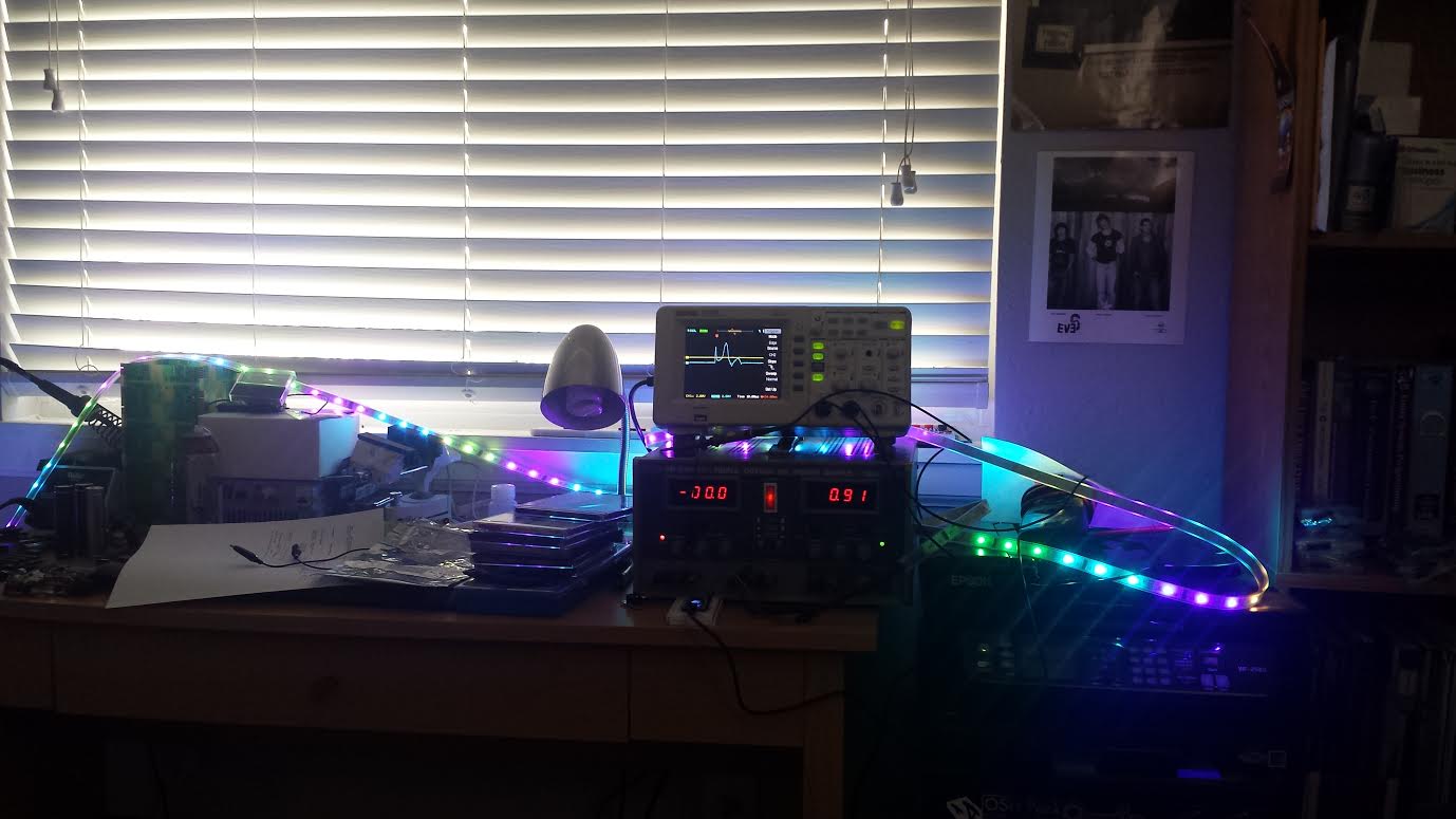
I used an LPC1768 Mbed microcontroller (because it’s super easy) and made a demo program with some simple animations. The strip is 30 LEDs per meter, 5 meters long. Each LED ‘pixel’ is a group of 3 RGB LEDs and they all show the same color. So there are 50 groups of 3 in my 5 meter strip. The way I drive the LEDs is I make a uint16_t array in RAM for the 50 pixels, then create a timer to run through the array and send it out to the strip using the SPI hardware. With 8 bytes of reset, 100 bytes of data, at 500KHz I was able to address the whole strip in about 4ms. I set my timer to update the strip at 10ms, giving me a 100Hz refresh rate.
The rest of the application just writes the data array in memory and lets the timer clock it out to the strip. I included the code here with 4 demos. This will build in the Mbed compiler and uses the P5 & P6 SPI pins on the LPC1768 for data and clock. It should be pretty straight forward to port to an Arduino or other microcontroller, just setup a timer and update the SPI config and write functions.
Here is a video of the demos in action:
And the source file: ledstrip_mbed_demo.cpp
Enjoy, Drew
Cool, I have been searching for info on these strips. Is this one of those with the 10 pin connector? I’m wondering if you have any schematics of how your demo is wired? I have one of these strips that came with a non-working remote and want to play with controlling it. Thanks
These strips have a 4-pin JST style connector. +12V, Data, Clock, Ground. Here is a link to some:
http://www.dhgate.com/product/wholesales-4pin-jst-connector-water-p-cable/212823671.html#sb1-9-1a|2598674737
Was thinking to do this with Christmas lights next year. Thanks for doing the sacrificial experimentation that will save me a lot of steps. If I have any questions, I’ll know where to go. Thanks for your informative articles!
i have bought those lpd6803 from the led color ,also i bought some sk6812wwa sk6812rgbw from them ,http://www.szledcolor.com/